Servic Sentinel Ground monitors are for low-medium volt- age circuits to monitor continuously the grounding circuit to assure ground wire continuity.
Note 1: Isolate all power before attempting to install or repair this unit.
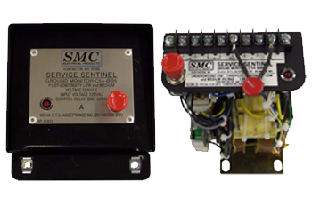
Switch Gear Unit
For wiring instructions see terminal connections diagram. The ground wire from cable being monitored must go through C.T. before being terminated to switchgear case or to the optional inverse parallel Diode Assembly (A2596). Therefore, the line plug and receptacle must be isolated from the ground wire. A flexible ground strap must be connected between the plug housing and switchgear unit enclosure. It must have the same current rating as the ground conductor.
Note 2: The A2596 Diode Assembly is provided for all long- wall applications & is an optional feature in other cases. Whenever the Diode Assembley is re-installed the Diode Assembley connections and ground connections should be checked against drawings to insure freedom from nuisance tripping.
4 Parts of Ground Monitors
Power Supply - derived from a 120/15 VAC constant voltage transformer with a secondary voltage of 15 VAC + 10% over a primary voltage range of 150/80 volts AC. Ground Loop Resistance Circuit - monitors the grounding circuit. The Ground Monitor Relay energizes if the combined pilot to ground wire resistance is less than 10 ohms and deenergizes if the combined resistance exceeds 75 ohms.
Ground Monitor Relay - special relay that cannot be energized by alternating current. If a pilot to ground fault exsits, shorting out the diode at the machine, the ground monitor relay will deenergize and trip the power circuit breaker.
Ground Wire Sensor - monitors the level of current flowing through the ground wire. If the ground wire is broken, the Ground Sensor Relay would sense insufficient current flowing through the ground wire and trip the power circuit breaker.